A milling route matched to project stage and quantity.
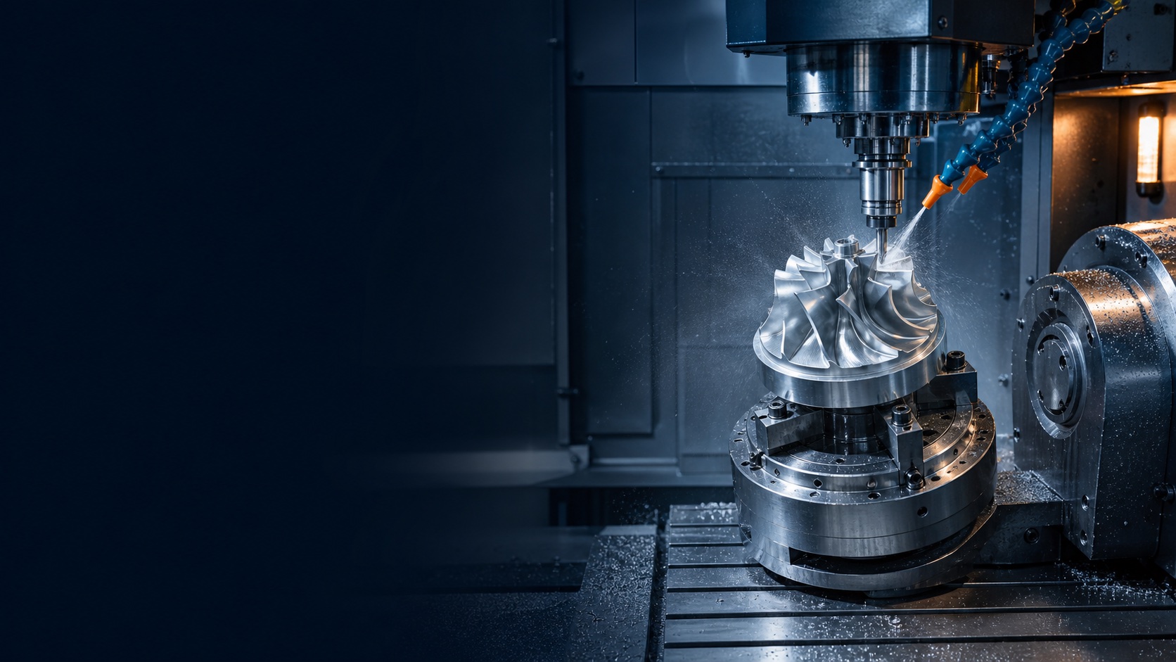
CNC milling service
Precision Features. Practical Production.
CNC milling for housings, brackets, plates, manifolds, fixtures, and complex prismatic parts—planned around your geometry, material, tolerances, finish, and inspection requirements.
Setup strategy selected around access and part complexity.
Material behavior considered during process planning.
Critical features and records defined before production.
Subtractive manufacturing
Turn Solid Stock Into Functional Geometry
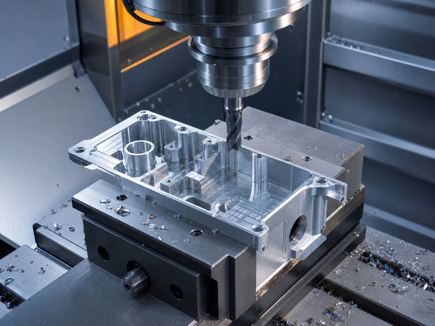
CNC milling uses rotating cutting tools to remove material from a secured workpiece. It is well suited to non-rotational parts with flat faces, pockets, slots, bores, hole patterns, threads, contours, and accurately related features.
Before machining, we review tool access, workholding, datum strategy, internal radii, wall thickness, pocket depth, tolerance relationships, and the surfaces that must remain cosmetic.
Machining strategy
The Right Number of Axes for the Part
More axes are not automatically better. The practical route is the one that reaches the required features with controlled setups, suitable tools, and a clear inspection plan.
01 / 3-AXIS
Efficient Prismatic Milling
Suitable for plates, brackets, housings, pockets, planar faces, and features accessible from standard orthogonal setups.
02 / INDEXED
Multi-Side Access
Rotary positioning can expose additional faces and angled features while reducing manual reorientation and datum transfers.
03 / 5-AXIS
Complex Geometry
Multi-axis motion can support compound angles, contoured surfaces, deep access, and complex parts where fewer setups improve consistency.
Typical milled features
Built for More Than Flat Surfaces
Feature combinations determine cutter selection, tool reach, workholding, cycle time, and the inspection method.
Faces & Shoulders
Controlled planar surfaces, steps, bosses, datums, and perpendicular relationships.
Pockets & Cavities
Open or enclosed pockets with tool-compatible depth, radii, and chip evacuation.
Slots & Profiles
Keyways, channels, edge profiles, curves, and contoured external geometry.
Holes & Threads
Drilled, bored, reamed, countersunk, counterbored, tapped, or thread-milled features.
Multi-Side Features
Related holes, ports, flats, and interfaces distributed across several part faces.
3D Contours
Freeform surfaces and transitions requiring controlled step-over and tool orientation.
Design for milling
Small Design Choices Can Simplify the Process
Final decisions depend on the complete part, but these principles help reduce unnecessary setups, specialty tooling, deflection, and inspection complexity.
Rotating cutters naturally leave radiused internal corners. A larger practical radius usually allows a stronger tool and more efficient machining.
Very deep narrow pockets require longer tools, which can increase deflection, vibration, and cycle time.
Thin sections can move under cutting and clamping forces; material, height, access, and adjacent geometry all matter.
Apply tight tolerances and GD&T where assembly or performance needs them, and identify the datums that connect critical features.
Material options
Material Behavior Is Part of the Plan
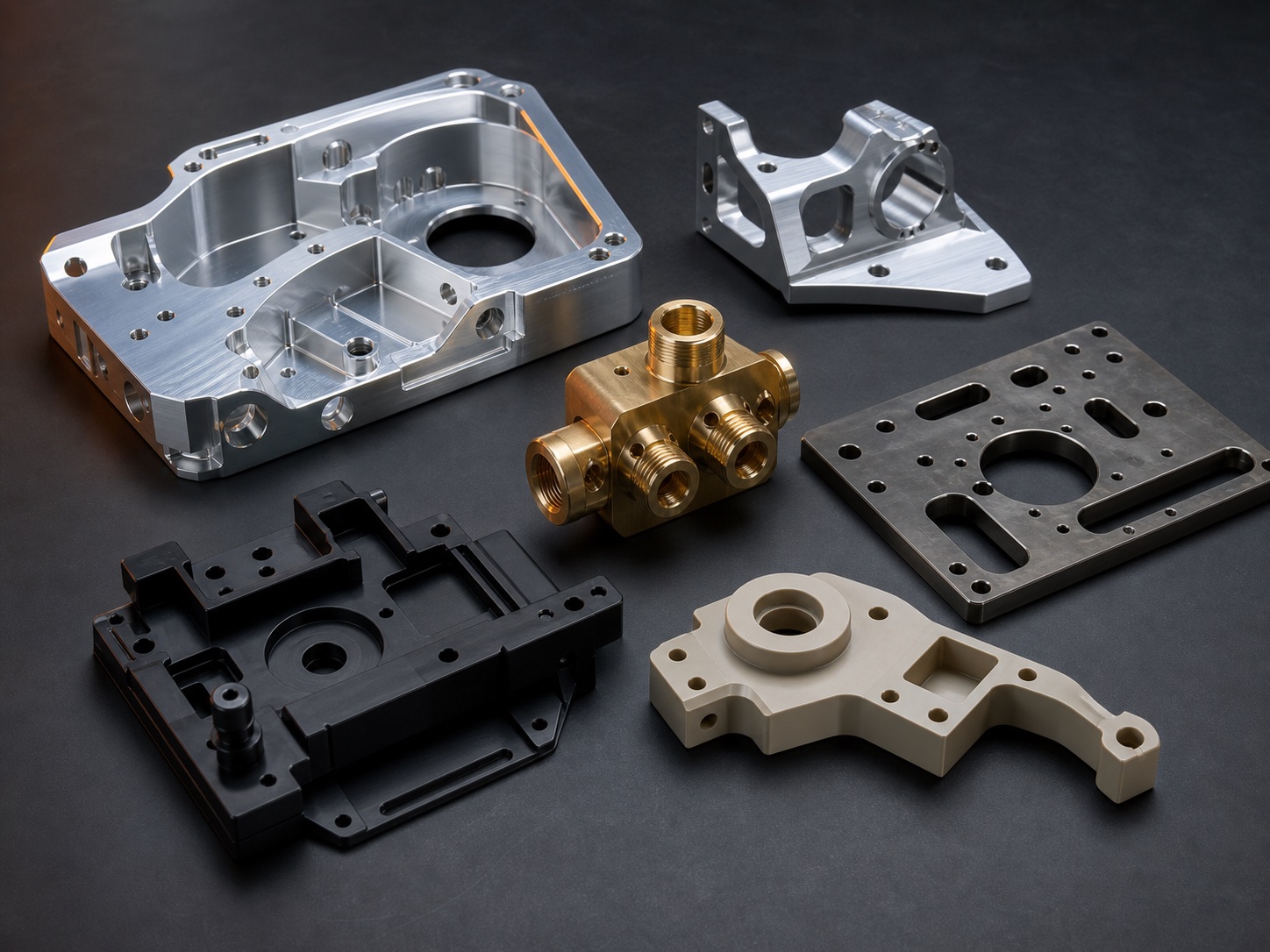
Machinability, stability, strength, heat response, burr formation, cosmetic requirements, and post-processing all influence the milling approach.
Metals
- Aluminum alloys
- Stainless steel
- Carbon and alloy steels
- Brass and copper alloys
- Titanium and project-specific alloys
Engineering Plastics
- Acetal / POM
- Nylon
- ABS and polycarbonate
- PTFE
- PEEK and application-specific polymers
Controlled workflow
From CAD Review to Released Parts
- 01
Review
Confirm files, revisions, material, quantity, critical features, finish, and records.
- 02
Plan
Select stock, setups, workholding, tools, toolpaths, and inspection checkpoints.
- 03
Mill
Machine the part with in-process checks positioned around important features.
- 04
Finish & Verify
Deburr, coordinate required finishing, complete inspection, and prepare documentation.

Quality planned up front
Measure the Features That Control Function
Inspection scope is aligned with drawing requirements, feature relationships, agreed sampling, and the documentation requested for the order.
- Drawing and revision review
- First-article checks when required
- Critical-feature verification
- Inspection records by agreed scope
Start with the manufacturing inputs
Send Your CNC Milling Project
Share the 3D model, current 2D drawing, material, quantity, finish, critical tolerances, inspection requirements, and target delivery timing.
Discuss Your Project