A turning route aligned with project stage and quantity.
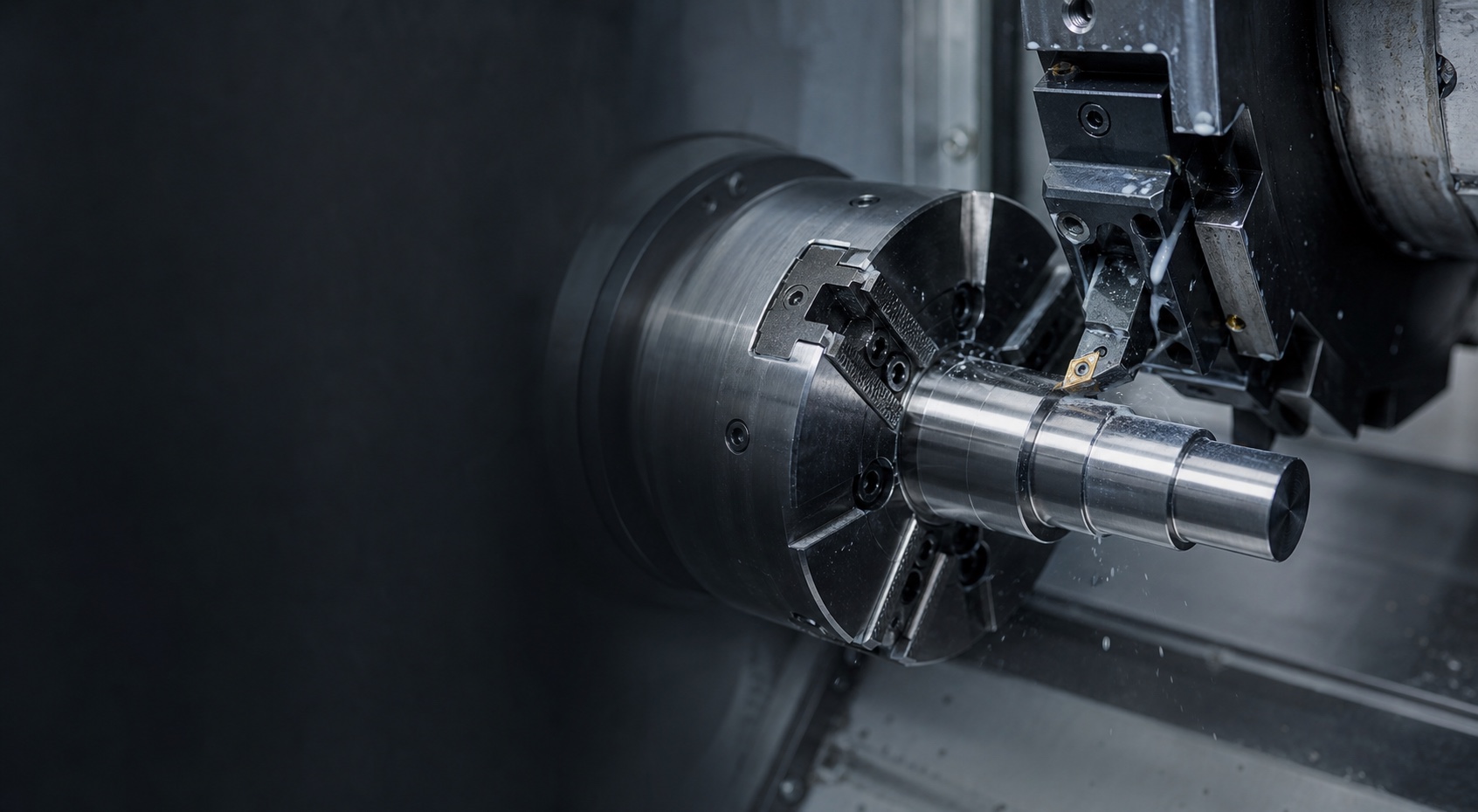
CNC turning service
Rotational Parts. Controlled Relationships.
CNC turning for shafts, sleeves, bushings, spacers, fittings, pins, rollers, and other rotational components—planned around concentricity, runout, threads, surface requirements, and inspection needs.
External and internal geometry planned as related features.
Functional details reviewed against access and tooling.
Datums and critical relationships defined before machining.
Subtractive manufacturing
Rotate the Workpiece, Control the Profile
In CNC turning, the workpiece rotates while cutting tools move along controlled paths. The process is particularly effective for parts whose primary geometry is organized around a common axis.
Before machining, we review stock form, chucking and support, datum structure, diameter relationships, bore access, groove and thread geometry, parting strategy, surface finish, and any secondary milled features.
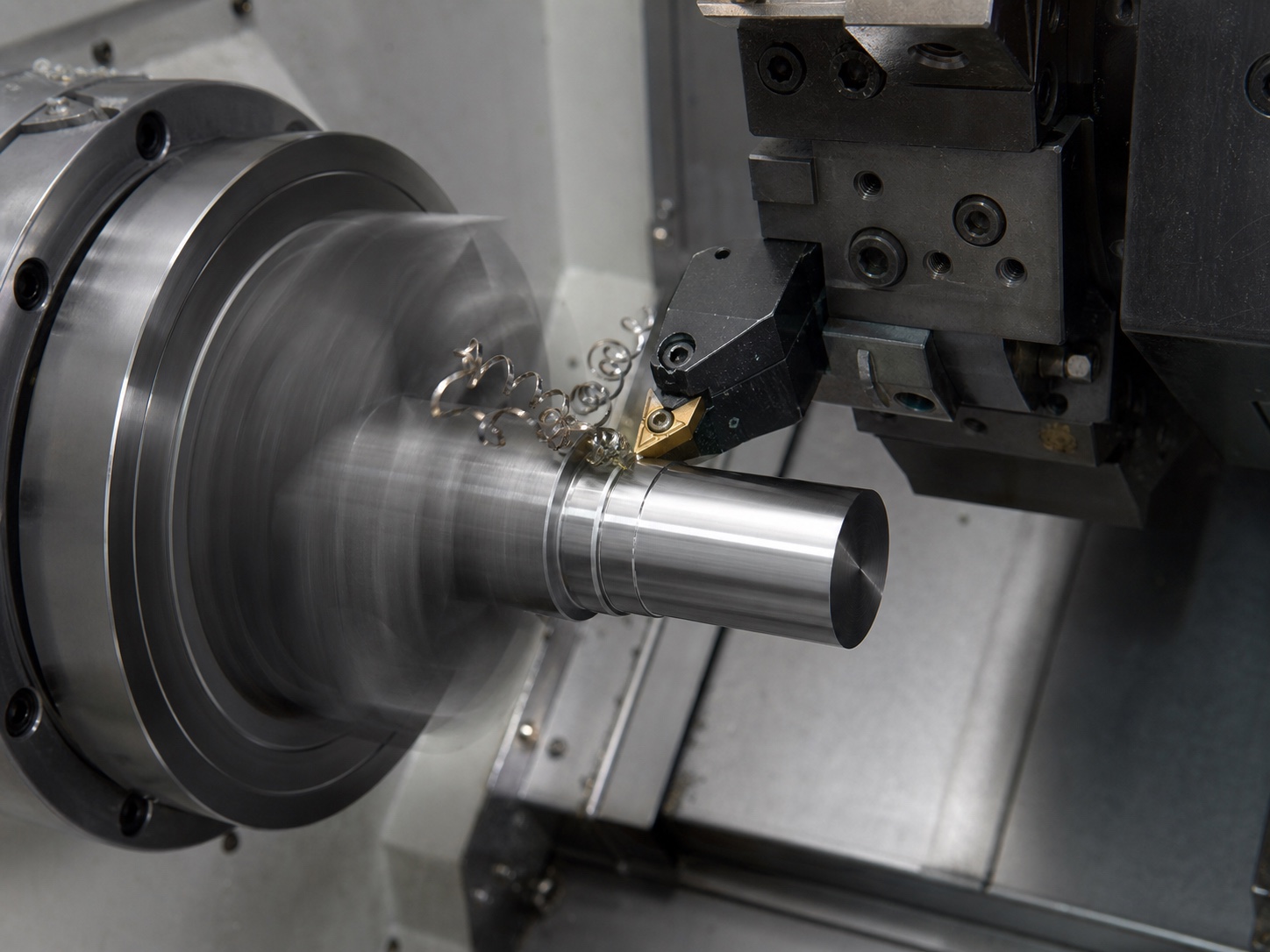
Process strategy
From Standard Turning to Mill-Turn Features
The practical route depends on part symmetry, feature access, production quantity, and whether non-rotational details should be completed in the same setup or a controlled secondary operation.
01 / TURNING
Core Rotational Geometry
Facing, outside and inside diameters, tapers, bores, grooves, shoulders, chamfers, threads, and parting operations.
02 / LIVE TOOLING
Secondary Features
Where equipment and geometry permit, driven tools can add flats, slots, axial or radial holes, and related milled details.
03 / SECOND OP
Controlled Handoffs
Complex cross-features or restricted access may be completed through a planned milling, drilling, EDM, or finishing operation.
Typical turned features
Geometry Built Around an Axis
Feature relationships—not the feature list alone—drive setup, tool selection, support, cycle planning, and measurement.
Faces & Diameters
Controlled lengths, shoulders, outside diameters, steps, tapers, and cylindrical datums.
Bores & Internal Profiles
Drilled, bored, reamed, counterbored, tapered, or profiled internal geometry.
Grooves & Undercuts
External or internal reliefs, seal grooves, retaining-ring features, and thread runouts.
External & Internal Threads
Threaded features reviewed for form, pitch, class, engagement, lead-in, and inspection method.
Axial & Radial Holes
On-axis holes and cross-features coordinated with turning or live-tool operations.
Flats, Slots & Keyways
Non-rotational details completed with suitable live tooling or a controlled secondary setup.
Design for turning
Protect Rigidity, Access, and Datum Logic
Final manufacturability depends on the complete part and material, but these principles help avoid unstable cutting, difficult inspection, and unnecessary secondary operations.
High length-to-diameter ratios can increase deflection and chatter; support method, cutting forces, material, and finish requirements all matter.
Grooves, shoulders, threads, and deep bores need practical tool access, clearances, and runout or relief features.
Thin cylindrical sections and deep small-diameter holes can amplify heat, vibration, distortion, and chip-control challenges.
Identify the datums, fits, concentric features, runout controls, sealing surfaces, and thread requirements that govern performance.
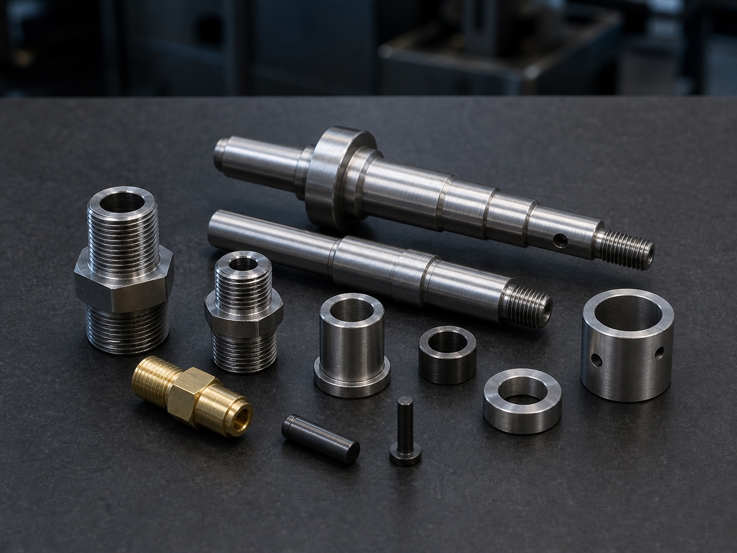
Material options
Material Response Shapes the Turning Plan
Chip behavior, work hardening, thermal expansion, rigidity, burr formation, thread quality, and cosmetic expectations influence tools, parameters, support, and inspection.
Metals
- Aluminum alloys
- Stainless steel
- Carbon and alloy steels
- Brass and copper alloys
- Titanium and project-specific alloys
Engineering Plastics
- Acetal / POM
- Nylon
- ABS and polycarbonate
- PTFE
- PEEK and application-specific polymers
Controlled workflow
From Drawing Review to Released Parts
- 01
Review
Confirm models, drawings, revisions, material, quantity, critical features, finish, and records.
- 02
Plan
Select stock, workholding, support, operation sequence, tooling, and inspection checkpoints.
- 03
Turn
Machine rotational features and coordinate required live-tool or secondary operations.
- 04
Finish & Verify
Deburr, complete finishing, inspect drawing requirements, and prepare agreed documentation.

Quality planned up front
Verify Size, Form, and Feature Relationships
Inspection scope is aligned with the drawing, functional datums, fits, threads, runout or concentric relationships, sampling plan, and requested documentation.
- Drawing and revision review
- First-article checks when required
- Diameter, length, thread, and runout verification
- Inspection records by agreed scope
Start with the manufacturing inputs
Send Your CNC Turning Project
Share the 3D model, current 2D drawing, material, quantity, finish, critical tolerances, thread specifications, inspection requirements, and target delivery timing.
Discuss Your Project