Programmed through-profiles, slots, punches, dies, and inserts.
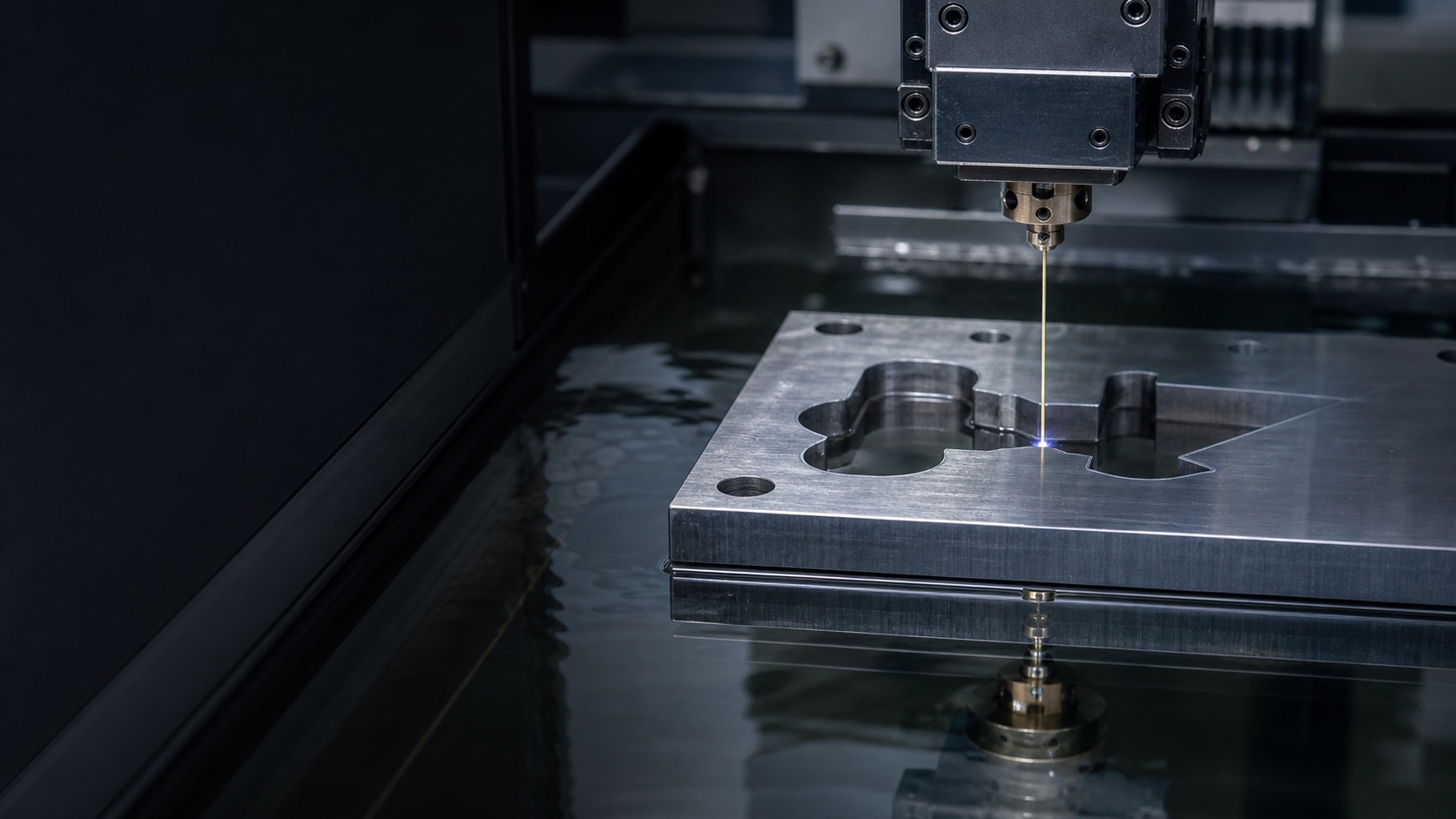
Electric discharge machining
Complex Conductive Geometry. No Cutting Contact.
EDM support for hardened tooling, intricate profiles, narrow slots, blind cavities, small holes, and features where conventional cutting access or force becomes impractical.
Shaped electrodes for cavities and difficult blind features.
Process planning based on material, condition, and geometry.
Critical size, profile, position, and surface requirements defined up front.
Controlled spark erosion
Remove Conductive Material Through Electrical Discharge
Electrical discharge machining removes small amounts of material through controlled pulses across a narrow gap between an electrode and an electrically conductive workpiece. A dielectric fluid controls the discharge and carries away debris.
Because the electrode does not cut through direct mechanical contact, EDM is useful for hardened materials, delicate sections, small internal details, deep or restricted features, and profiles that are difficult to reach with conventional cutters.
EDM process selection
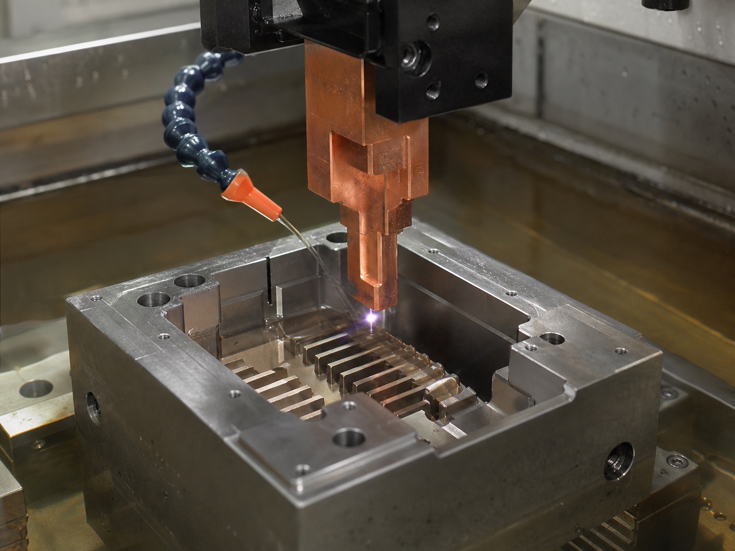
Choose the Electrode Strategy Around the Feature
Wire, shaped electrodes, and tubular electrodes solve different geometry problems. The correct route depends on whether the feature is through or blind, its access, material, depth, finish, and inspection needs.
01 / WIRE EDM
Through-Cut Profiles
A continuously moving wire follows a programmed path through conductive stock for profiles, slots, punches, dies, inserts, and cut-off features.
02 / SINKER EDM
Blind Cavities & Forms
A shaped copper or graphite electrode reproduces its geometry into the workpiece for cavities, ribs, recesses, and restricted internal details.
03 / HOLE EDM
Small Starting Holes
Tubular-electrode EDM can create small or deep holes and can prepare wire-start access where a closed internal contour is required.
Typical EDM applications
Features Beyond Conventional Tool Access
EDM is selected for the geometry and material condition—not simply because a feature appears small or precise.
Punches & Dies
Matched profiles, trim tools, blanking details, extrusion tooling, and precision inserts.
Narrow Slots
Fine through-slots, reliefs, key-like features, and restricted-width profiles.
Complex Contours
Programmed internal and external profiles in hardened conductive workpieces.
Blind Cavities
Mold details, pockets, ribs, textural features, and internal forms produced with shaped electrodes.
Small & Deep Holes
Start holes, cooling passages, venting features, and project-specific hole geometry.
Hardened Components
Tool steels, carbide and other conductive materials where post-heat-treatment machining is required.
Design for EDM
Plan the Current Path, Access, and Finished Surface
EDM capability depends on the complete geometry, but these decisions help determine whether wire, sinker, hole EDM, or conventional machining is the practical route.
EDM requires an electrically conductive workpiece. Material grade, heat-treatment condition, coatings, and composite structure should be identified.
Wire EDM creates through-features. Closed internal profiles generally require a suitable start hole and a plan for retaining or removing the cut slug.
Blind cavities and deep narrow features need practical electrode geometry, working clearance, debris removal, and stable process conditions.
EDM is a thermal process. Specify surfaces where roughness, recast layer, edge condition, fatigue, sealing, or downstream polishing matters.
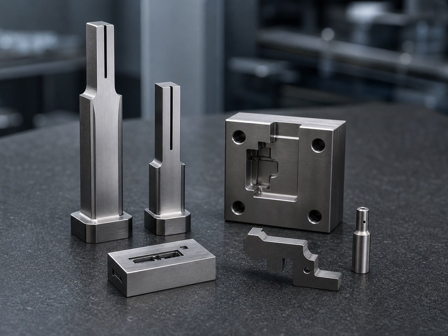
Materials and fit
Hardness Is Not the Only Decision
EDM can process many conductive materials regardless of conventional machinability, but conductivity, thickness, heat treatment, flushing, desired surface, and downstream performance still shape the plan.
Common Conductive Materials
- Tool and mold steels
- Stainless and alloy steels
- Aluminum and copper alloys
- Titanium alloys
- Carbide and project-specific materials
Typical Reasons to Use EDM
- Material is already hardened
- Feature access limits cutting tools
- Mechanical cutting force is undesirable
- Through-profile is intricate or narrow
- Blind cavity needs a shaped electrode
Controlled workflow
From Feature Review to Released Parts
- 01
Review
Confirm geometry, material, heat treatment, quantity, critical surfaces, tolerances, and records.
- 02
Plan
Select EDM type, workholding, start holes or electrodes, offsets, roughing and finish passes, and inspection points.
- 03
Machine
Control discharge, dielectric condition, flushing, wire or electrode path, and feature sequence.
- 04
Verify
Clean, inspect critical geometry and surface requirements, then prepare agreed documentation.

Quality planned up front
Verify the Geometry EDM Was Selected to Protect
Inspection scope is aligned with profile, size, position, taper, cavity depth, surface condition, datum relationships, sampling, and required records.
- Drawing and revision review
- Start-hole, electrode, and offset planning
- Profile, position, depth, and surface verification
- Inspection records by agreed scope
Start with the manufacturing inputs
Send Your EDM Project
Share the 3D model, current 2D drawing, material and heat treatment, quantity, critical features, surface requirements, inspection scope, and target delivery timing.
Discuss Your Project