Joint Housings
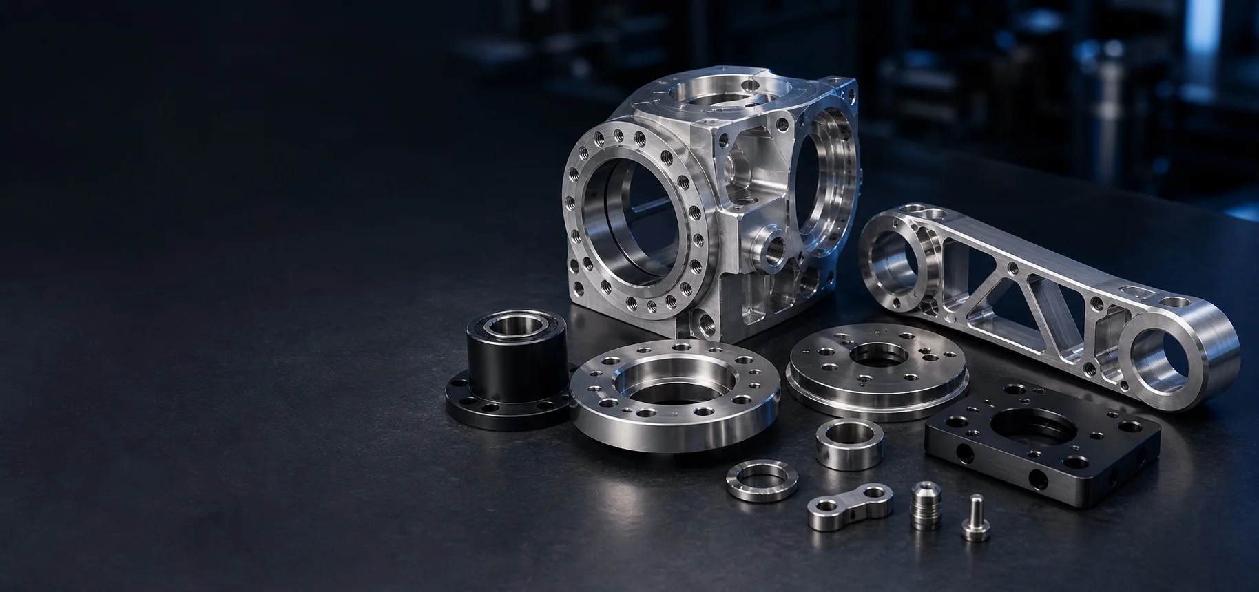
Complex housings with bearing seats, cable passages, bolt circles, and accurate multi-face interfaces.
Application considerations
Precision-manufactured components for robotic systems that depend on accurate motion, structural efficiency, and reliable assembly.
Project guide
Describe fits, datum relationships, moving clearances and post-finish acceptance against mating parts. Separate component inspection from system performance validation.
Precision in every movement
Robotic systems place demanding requirements on joint alignment, weight, rigidity, bearing interfaces, and assembly repeatability. Discuss the component geometry, machining route, finishing, inspection and assembly scope against those interfaces.
Identify the project stage and the interfaces that control movement and fit. Agree which component checks are included and which system tests remain with the designer.
Component examples to discuss
Precision manufacturing for the structural and motion components used from the robot base to the working end effector.
Complex housings with bearing seats, cable passages, bolt circles, and accurate multi-face interfaces.
Lightweight links and connectors with machined pockets, structural ribs, and controlled joint alignment.
Tooling plates, adapter blocks, gripper mounts, and interfaces designed for accurate changeover.
Precision flanges, bearing housings, spacers, sleeves, and locating parts for controlled motion.
Connected capabilities
Combine the capabilities required for your robotic component or subsystem.
Complex geometry
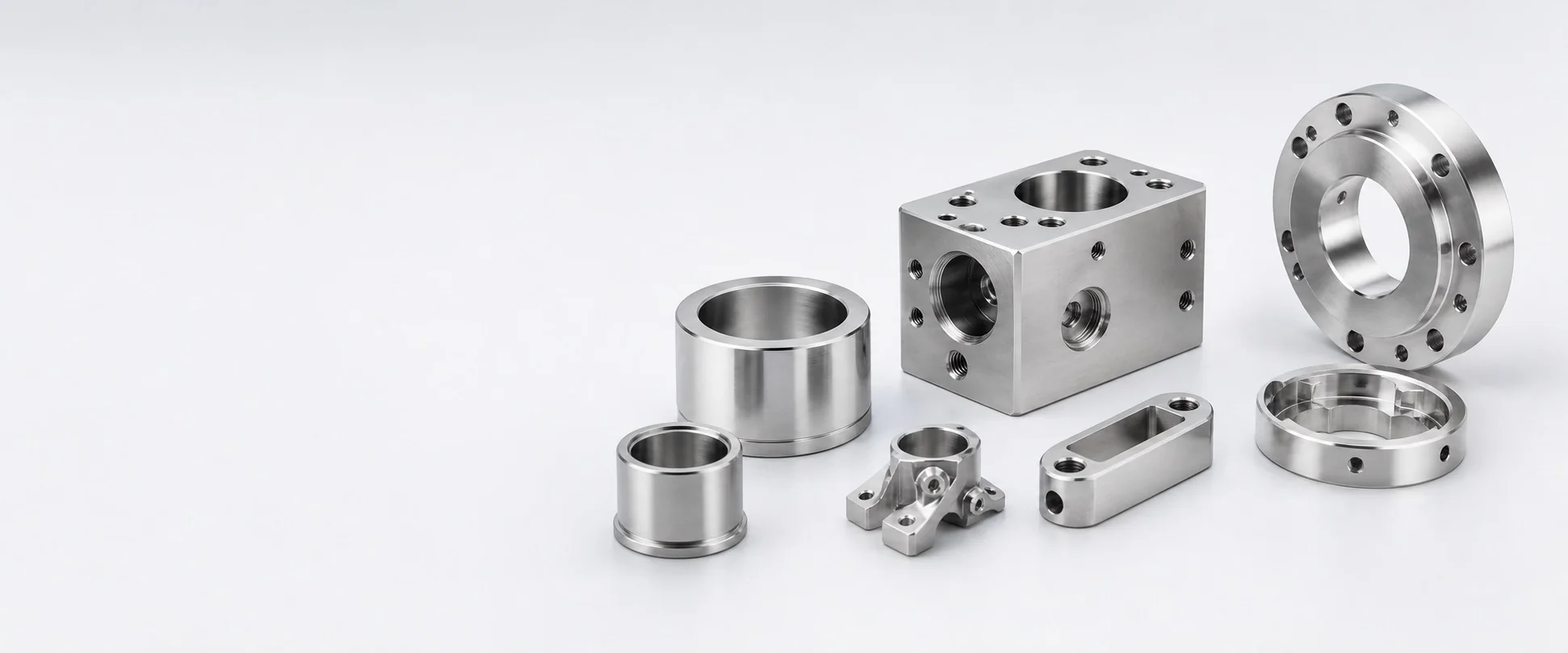
Joint housings, links, flanges, tooling interfaces, and close-tolerance motion components.
Explore CNC machining →Durable surfaces
Coordinated finishing for appearance, wear resistance, corrosion protection, and component identification.
Explore surface finishing →Ready for installation
Component assembly support for bearings, fasteners, inserts, and related robotic subassemblies.
Explore assembly support →Decision guide
For parts used in a moving assembly, size limits alone may not describe function. Identify the mating components, datum relationships, clearances and final surface condition that affect rotation, alignment or assembly.
Scroll horizontally to compare all columns.
| Design scenario | Requirement to make explicit | Route or acceptance discussion |
|---|---|---|
| Shaft, sleeve or bushing | Mating fits, datum axis and required runout or alignment | Discuss turning and how relationships will be measured |
| Housing or joint interface | Bearing or mounting locations, wall sections and reference datums | Review milling access, support and the relevant assembled condition |
| Connecting or lightweight part | Required envelope, interfaces and load assumptions supplied by the designer | Review manufacturability without treating material removal as proof of strength |
| Finished moving or contacting surface | Masking, texture and whether dimensional requirements apply after finishing | Agree final inspection conditions and any test outside component manufacture |
Component manufacture and dimensional inspection do not certify robot safety, payload, fatigue life or system performance. Those conclusions require the designer’s validation under the intended operating conditions.
Guide updated . Confirm the manufacturing and inspection scope for your actual order.
Start your robotics project
Share your part files, quantities, materials, finishes, and quality requirements. Our team will review the details and respond by email.
Discuss Your Application