Move from suitable 3D data to physical parts without dedicated production tooling.
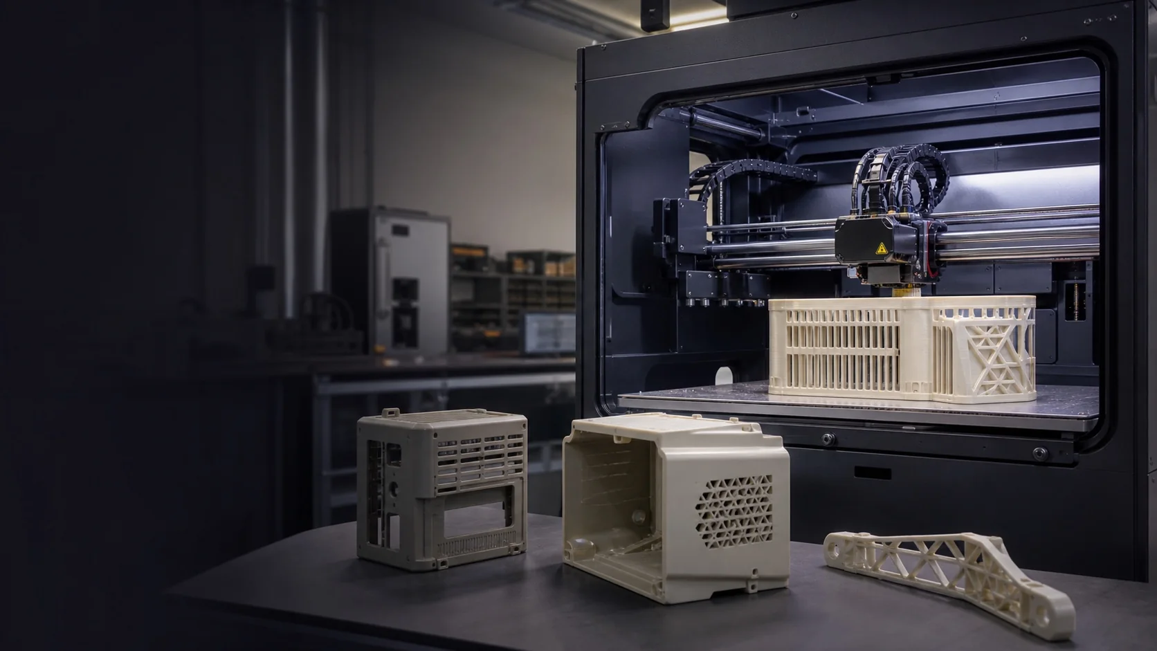
Industrial 3D printing
Industrial 3D Printing Services for Functional Parts
Project-specific additive manufacturing support for concept models, fit checks, functional prototypes, fixtures, complex internal geometry, customized parts, and selected low-volume applications.
Project guide
How do you choose a printing route?
Select the route around the intended test or end use. Material, orientation, surface requirements and post-processing all affect whether a printed part meets the requirement.
Build acceptance guide
Define what the printed build must prove
What should be agreed before a printed part is built?
State the intended use and acceptance criteria first. Review the process, material grade, orientation, support removal and post-processing against those criteria before approving the build.
Scroll horizontally to compare all columns.
| Build requirement | Information to supply | Decision before approval |
|---|---|---|
| A fit model must locate on existing parts | Mating geometry, critical interfaces and the test assembly | Agree which dimensions and fit checks matter; identify any permitted local rework |
| Loads act along a particular direction | Load direction, environment, intended test and required material evidence | Review orientation and process limitations; a shared material name is not proof of equivalent performance |
| Internal spaces or cosmetic faces need cleanup | Accessible openings, prohibited support marks and visible surfaces | Confirm support or powder removal access and the accepted surface condition |
| Results must be compared across builds | Model revision, selected route, material and post-processing scope | Record agreed build information and known deviations; approve changes before the next build |
Availability and suitability are confirmed for the actual project. A successful fit model does not by itself validate fatigue life, thermal performance or regulated end use.
Confirm the selected process and acceptance scope before approving the build.
Guide updated .
Create internal passages, organic forms, lattices, and consolidated assemblies where practical.
Match extrusion, resin, or powder-bed routes to the required evidence.
Plan support removal, cleaning, curing, finishing, inserts, and inspection from the start.
A family of additive processes
Choose the Process Before You Choose the Material Name
3D printing builds parts from digital data in successive layers, but extrusion, vat photopolymerization, and powder-bed fusion produce different surfaces, dimensional behavior, support needs, directional properties, and post-processing requirements.
The same general material label can behave differently across processes and build settings. Selection should begin with the part’s purpose, geometry, environment, loading, surface expectation, quantity, inspection needs, and whether the result is a model, a functional prototype, tooling, or an end-use component.
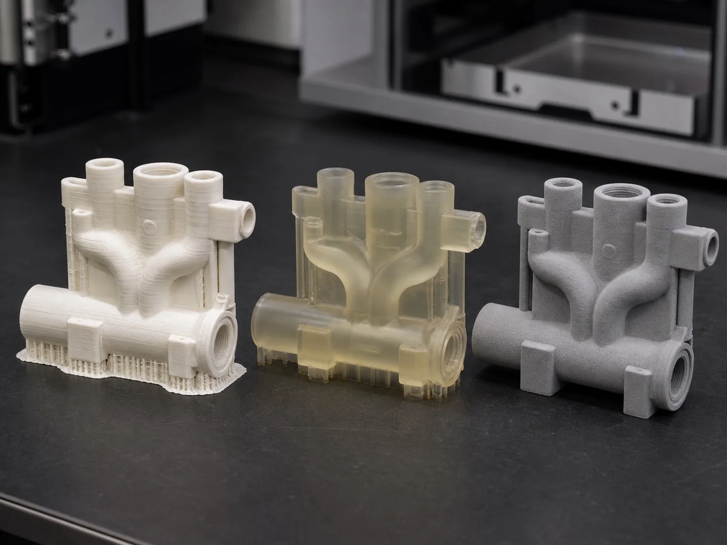
Typical polymer routes
Different Processes Solve Different Problems
Availability is confirmed per project. The correct route depends on geometry, required detail, mechanical behavior, finish, quantity, support access, and the intended use of the part.
01 / EXTRUSION
FDM / FFF
Useful for economical concept and functional parts in engineering thermoplastics, with visible layers and direction-dependent behavior considered in the build.
02 / RESIN
SLA / DLP
Suited to fine features, smooth surfaces, appearance models, patterns, and selected functional applications where resin behavior matches the test.
03 / POWDER BED
SLS / MJF
Supports durable nylon parts, nested builds, complex geometry, and many shapes without attached support structures, followed by depowdering and finishing.
Design for additive
The Build Strategy Is Part of the Design
Orientation, supports, layer direction, heat, powder removal, curing, and finishing can change the result. Review them before printing.
Walls & Fine Features
Wall thickness, pins, slots, text, ribs, and unsupported spans must suit the selected process, scale, and service load.
Orientation & Layer Direction
Build orientation affects surface quality, support contact, dimensional behavior, time, and strength across different directions.
Supports & Overhangs
Provide access for support removal and keep witness marks away from critical cosmetic, sealing, sliding, or mating surfaces.
Holes & Mating Features
Plan clearance, threads, inserts, reaming, machining allowance, and measurement access for interfaces that control fit.
Hollow Parts & Escape Paths
Include practical drain, vent, cleaning, curing, or depowdering access so trapped material does not compromise the part.
Surface & Tolerance
Separate as-printed expectations from surfaces that require sanding, coating, sealing, machining, or dimensional verification.
Design for additive manufacturing
Use Additive Freedom Deliberately
Complexity can be valuable, but unnecessary complexity still adds cleaning, inspection, support, distortion, and qualification risk.
Use ribs, shells, transitions, and local reinforcement with the build direction and actual service loads in mind.
Combine parts only when it improves assembly, weight, flow, reliability, customization, or total manufacturing effort.
Orient or add stock so support contact, layer stepping, powder texture, and finishing do not undermine functional interfaces.
Make internal channels accessible to remove residue and define how critical geometry will be inspected after the build.
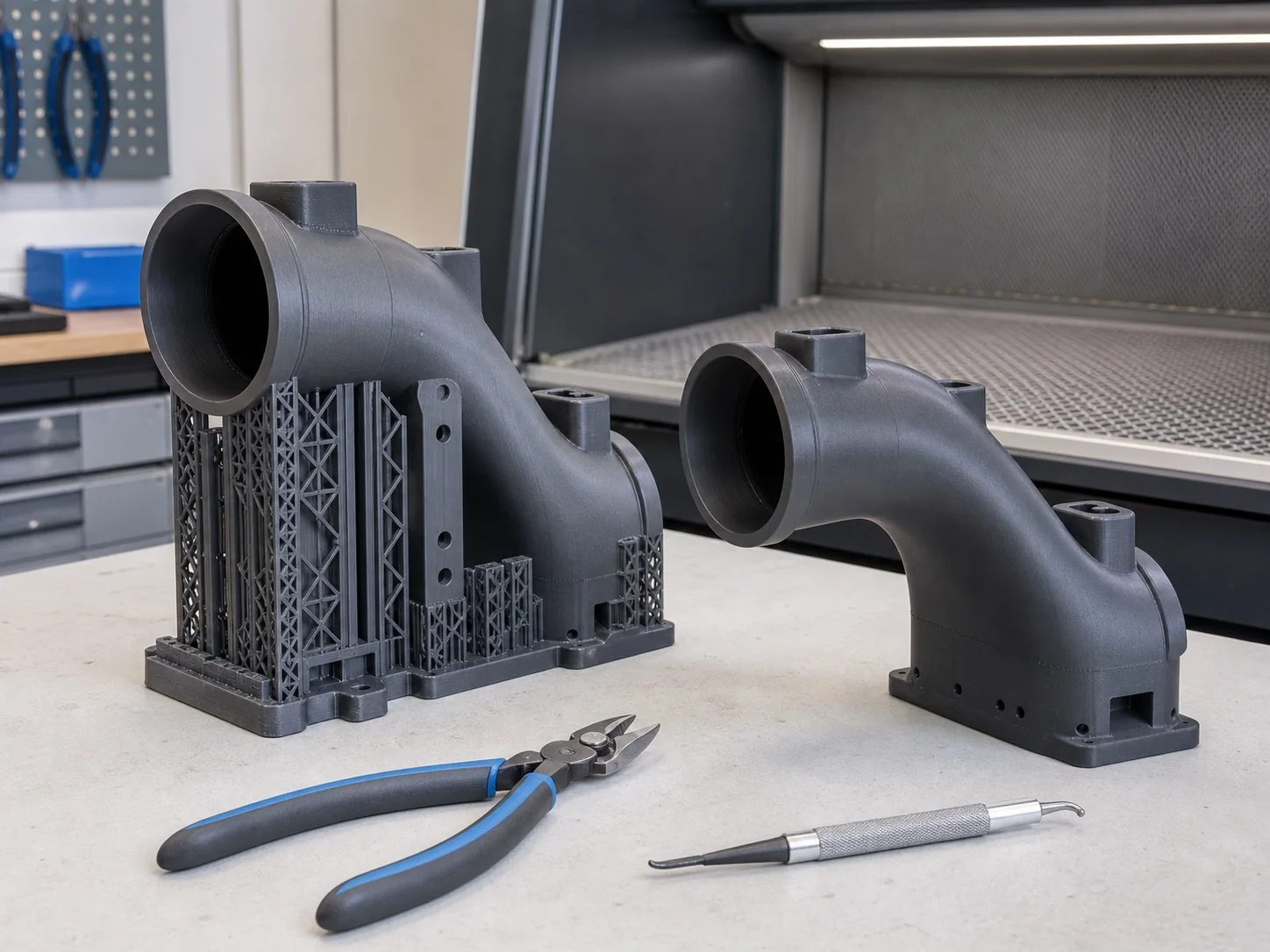
Materials and finishing
Specify the Performance, Not Only the Polymer
Printed material performance depends on process, grade, orientation, parameters, environment, and post-treatment. Requirements should describe what the part must do, not assume equivalence to an injection-molded or machined grade with a similar name.
Typical Material Families
- General and engineering thermoplastics
- Nylon and filled nylon systems
- Rigid, tough, flexible, or clear resins
- Heat- or environment-focused options
- Application-specific materials by review
Secondary Operations
- Support removal, cleaning, and curing
- Depowdering and surface smoothing
- Sanding, sealing, painting, or dyeing
- Threaded inserts and light assembly
- Critical-feature machining or inspection
Additive workflow
From 3D Data to Finished Printed Part
- 01
Define
Confirm use, quantity, environment, loads, interfaces, appearance, critical features, documentation, and target timing.
- 02
Prepare
Review geometry, choose process and material, set orientation, supports, nesting, compensation, and post-processing scope.
- 03
Build
Print under the selected route, monitor the build as appropriate, then cool, clean, depowder, or cure before handling.
- 04
Finish & Verify
Remove supports, complete agreed secondary operations, inspect critical requirements, and document known deviations.

Quality by agreed scope
Control the Digital Revision and the Physical Build
Inspection begins with the correct model and defined build route. Dimensional, visual, fit, and documentation scope should reflect the part’s purpose and the realities of the selected additive process.
- Model revision and build-route review
- Material, orientation, and post-process record
- Critical dimensions and interface checks
- Visual, fit, and known-deviation reporting
Start with the part requirements
Choose the Additive Route Around the Application
Share the 3D model and drawing, intended use, quantity, loading and environment, mating parts, critical dimensions, appearance requirements, preferred material, finishing needs, and target timing.
Discuss Your Printed Part